- Home
- Product
- Fuse
- Electrical Protection
- Fuse Holder and Fuse Base
- Copper Busbar
- PV System
- Busbar System
- Electric Meter Box
- Power Distribution Box
- Blog
- Projects
- Resource
- Solutions
- About Us
- Contact Us
- VR Visit


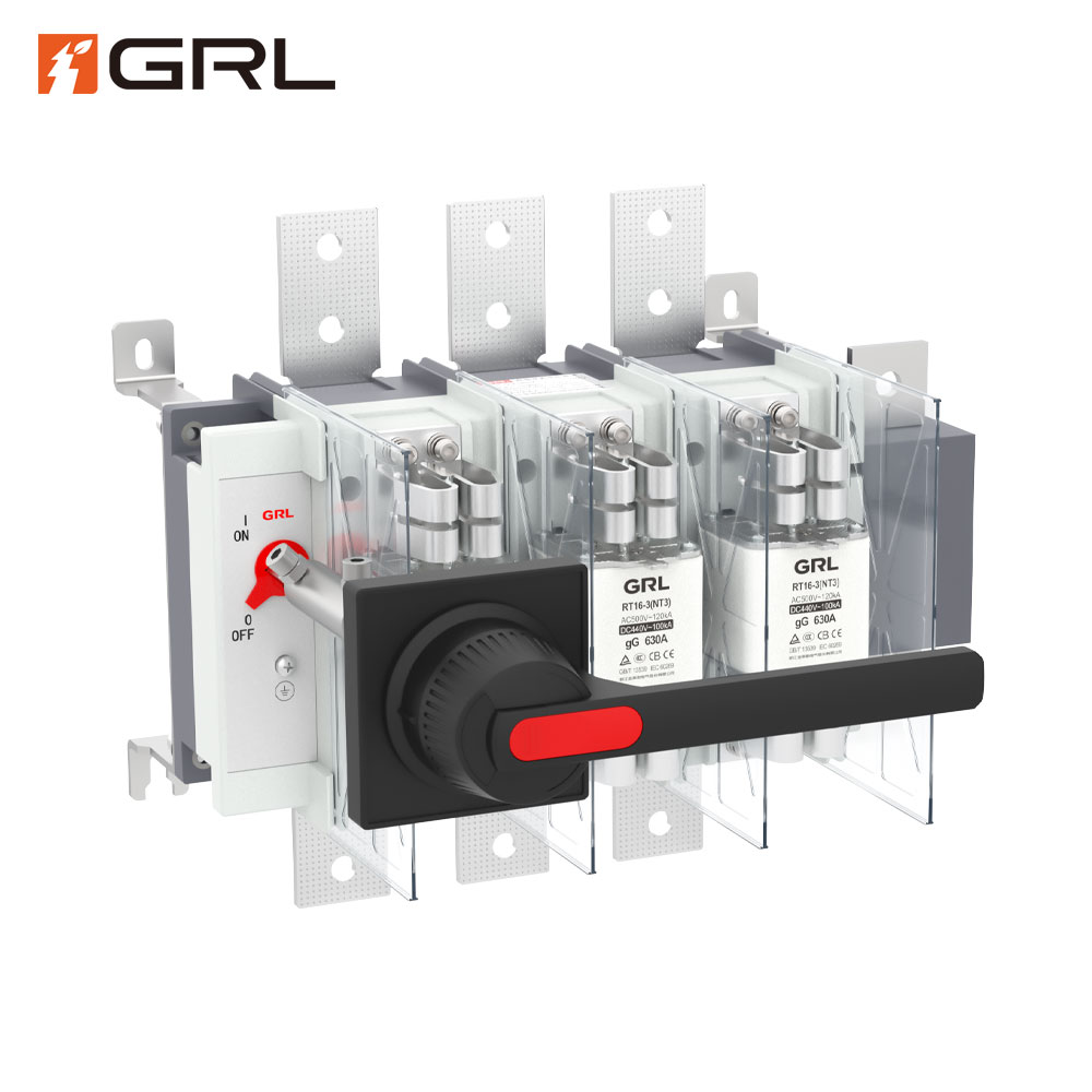
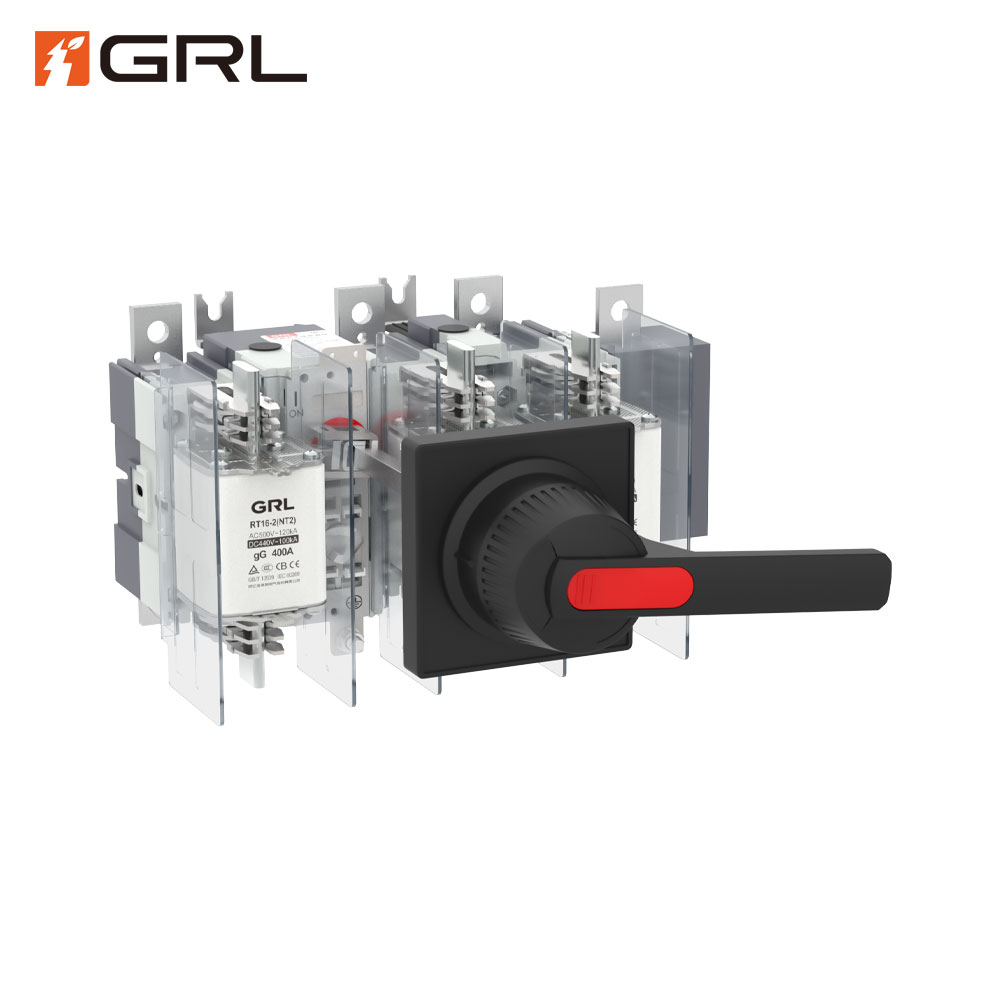

HH15 series disconnecting switch fuse group and disconnecting switch (hereinafter referred to as switch) include QSA series, QA series and QP series, which are mainly applicable to distribution circuits and motor circuits with high short-circuit current, as the main switch or main switch operated infrequently by hand. QSA series switches can be used for circuit short-circuit protection.
The switch complies with GB/T 14048.3 and IEC60947-3 standards and is widely used in higher drawer type low-voltage complete sets.
The ambient air temperature shall not be higher than +40 ℃, not lower than -5 ℃, and the average temperature within 24 hours shall not exceed +35 ℃.
The altitude of the installation site shall not exceed 2000m.
When the ambient air temperature is +40 ℃, the relative humidity shall not exceed 50%. At a lower temperature, a higher relative humidity is allowed, for example, 90% at 20 ℃. Special measures shall be taken for condensation occasionally caused by temperature change.
The pollution level of the surrounding environment is 3 poles.
The switch shall be installed in a place without significant shaking, shock vibration and rain and snow invasion. At the same time, the installation site shall be free of explosive dangerous media, and the media shall be free of gas and dust sufficient to corrode metal and damage insulation.
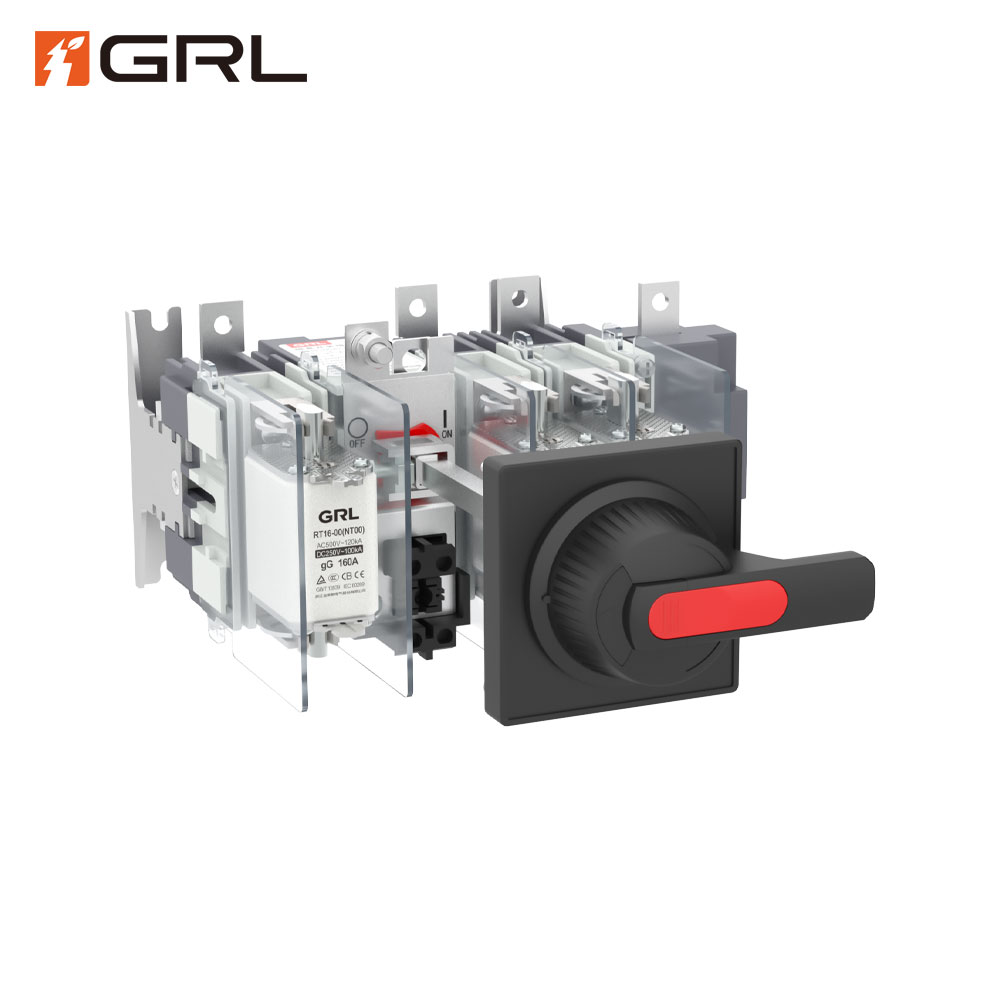
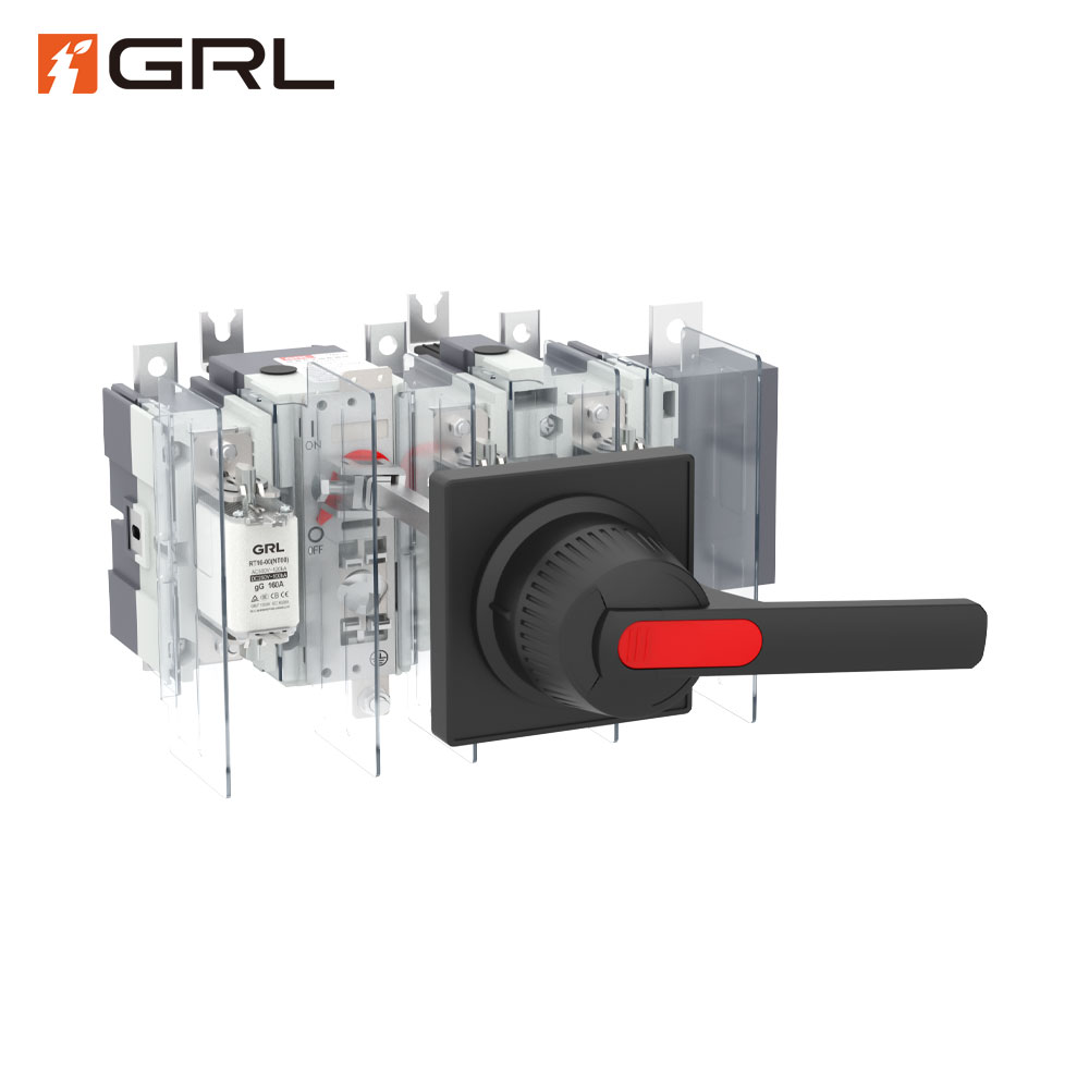
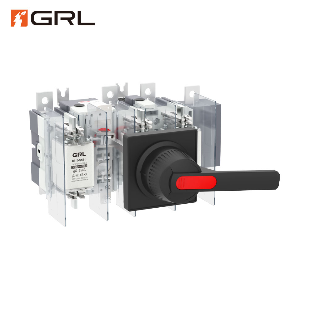
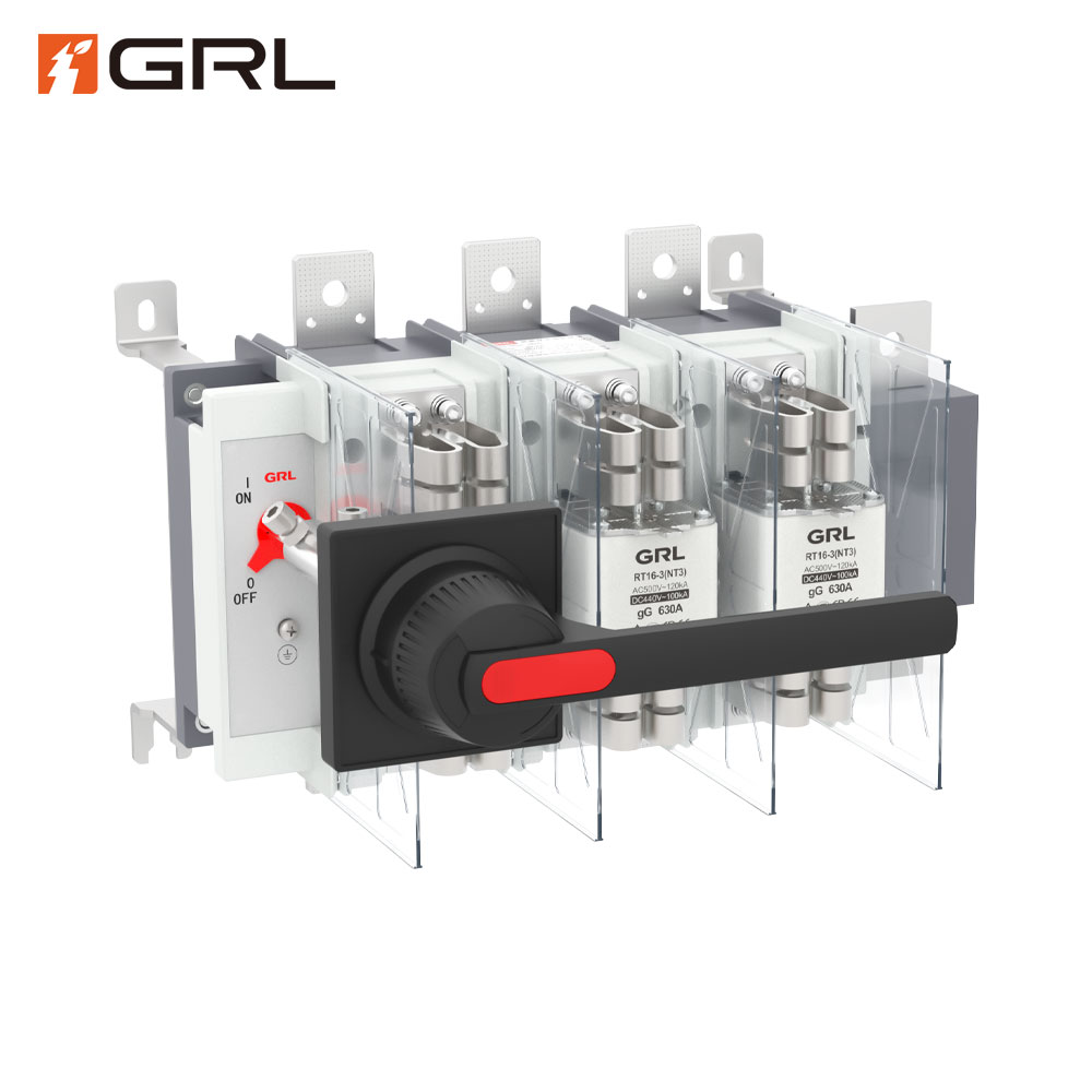
The switch adopts the front rotation operation mode, which is composed of operating mechanism, contact system, handle, etc.
The switch adopts a fully enclosed structure and is operated by spring energy storage. The closing and breaking speed of the switch is independent of the action speed of the operator, so as to ensure the safety of operators and equipment.
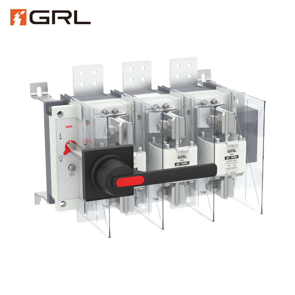
The switch is a contact system with unique performance. The moving contact system is directly formed from red copper bar. The moving contact piece is of bridge structure and has automatic adjustment function, so that it can effectively ensure line contact when connected with the static contact, thus ensuring the stability of product temperature rise.
The operating handle can be installed on the switch cabinet door. When the cabinet door is closed, the handle fits with the operating lever of the switch. When the switch is in the closed position, the handle is interlocked with the cabinet door to prevent the cabinet door from opening.
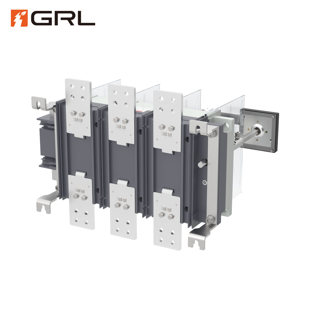
The switch is also equipped with an extension shaft, and the special length can be customized separately.
Read on what is isolator switch?

| Specifications | QSA- 125 | QSA- 160 | QSA- 250 | QSA- 400 | QSA- 630 | QSA- 800 | QSA- 1000 | QSA- 1250 | |
| Number of main poles | 3,3N,4 | 3,3N,4 | 3,3N,4 | 3,3N,4 | 3,3N,4 | 3,3N,4 | 3,3N,4 | 3,3N,4 | |
| Rated insulation voltage Ui | V | 1000 | 1000 | 1000 | 1000 | 1000 | 1000 | 1000 | 1000 |
| Rated impulse withstand voltage Uimp | kV | 12 | 12 | 12 | 12 | 12 | 12 | 12 | 12 |
| Rated working voltage Ue | V | 415/690V | 415/690V | 415/690V | 415/690V | 415/690V | 415/690V | 415/690V | 415/690V |
| Agreed heating current | A | 125 | 160 | 250 | 400 | 630 | 800 | 1000 | 1250 |
| Rated working current | A | 125/100 | 160/100 | 250/200 | 400/315 | 630/500 | 800/500 | 1000/800 | 1250/1000 |
| Rated limiting short-circuit current | kA | 100/50 | 100/50 | 100/50 | 100/50 | 100/50 | 100/50 | 100/50 | 100/50 |
| Mechanical life | time | 15000 | 12000 | 12000 | 12000 | 3000 | 3000 | 1000 | 1000 |
| Electrical life | time | 1000 | 300 | 300 | 300 | 200 | 150 | 100 | 100 |
| Fuse size |
| 00 | 00 | 1 | 2 | 3 | 3 | RSO(RS3)-1250 | 4 |
| Operating torque | Nm | 7.5 | 16 | 16 | 16 | 30 | 30 | 38 | 38 |
| Agreed heating current of auxiliary contact Ith 400V、AC-15A | 4 | 4 | 4 | 4 | 4 | 4 | 4 | 4 | |
| Specifications | QSA- 125 | QSA- 160 | QSA- 200 | QSA- 400 | QSA- 630 | QSA- 1000 | QSA- 1250 | QSA- 1600 | |
| Number of main poles | 3,3N,4 | 3,3N,4 | 3,3N,4 | 3,3N,4 | 3,3N,4 | 3,3N,4 | 3,3N,4 | 3,3N,4 | |
| Rated insulation voltage Ui | V | 1000 | 1000 | 1000 | 1000 | 1000 | 1000 | 1000 | 1000 |
| Rated impulse withstand voltage Uimp | kV | 12 | 12 | 12 | 12 | 12 | 12 | 12 | 12 |
| Rated working voltage Ue | V | 415/690V | 415/690V | 415/690V | 415/690V | 415/690V | 415/690V | 415/690V | 415/690V |
| Agreed heating current | A | 125 | 160 | 200 | 400 | 630 | 1000 | 1250 | 1600 |
| Rated working current:AC-23B | A | 12 | 160 | 200/160 | 400 | 630/400 | 1000/630 | 1250/1000 | 1600/1000 |
| Rated short-time withstand current Icw | Ka/1s | 5 | 5 | 5 | 12.6 | 12.6 | 25 | 50 | 50 |
| Mechanical life | time | 15000 | 15000 | 12000 | 3000 | 3000 | 3000 | 1000 | 1000 |
| Electrical life | time | 1000 | 1000 | 1000 | 300 | 300 | 150 | 100 | 100 |
| Operating torque | Nm | 7.5 | 7.5 | 7.5 | 16 | 16 | 30 | 38 | 38 |
| Agreed heating current of auxiliary contact Ith 400V、AC-15A | 4 | 4 | 4 | 4 | 4 | 4 | 4 | 4 | |
| Specifications | QSA- 250 | QSA- 400 | QSA- 630 | QSA- 1000 | QSA- 1250 | QSA- 1600 | QSA- 2000 | QSA- 2500 | |
| Number of main poles | 3,3N,4 | 3,3N,4 | 3,3N,4 | 3,3N,4 | 3,3N,4 | 3,3N,4 | 3,3N,4 | 3,3N,4 | |
| Rated insulation voltage Ui | V | 1000 | 1000 | 1000 | 1000 | 1000 | 1000 | 1000 | 1000 |
| Rated impulse withstand voltage Uimp | kV | 12 | 12 | 12 | 12 | 12 | 12 | 12 | 12 |
| Rated working voltage Ue | V | 415/690V | 415/690V | 415/690V | 415/690V | 415/690V | 415/690V | 415/690V | 415/690V |
| Agreed heating current | A | 250 | 400 | 630 | 1000 | 1250 | 1600 | 2000 | 2500 |
| Rated working current 690V:AC-21B | A | 250 | 400 | 630 | 1000 | 1250 | 1600 | 2000 | 2500 |
| Rated working current 415V:AC-22B | A | 250 | 400 | 630 | 1000 | 1250 | 1600 | 2000 | 2500 |
| Rated short-time withstand current Icw | Ka/1s | 8 | 25 | 25 | 25 | 50 | 50 | 60 | 60 |
| Mechanical life | time | 15000 | 15000 | 12000 | 12000 | 3000 | 3000 | 500 | 2000 |
| Electrical life | time | 1000 | 1000 | 200 | 150 | 100 | 100 | 100 | 100 |
| Operating torque | Nm | 16 | 16 | 16 | 30 | 38 | 38 | 38 | 38 |
| Agreed heating current of auxiliary contact Ith 400V、AC-15A | 4 | 4 | 4 | 4 | 4 | 4 | 4 | 4 | |


The ordering unit must indicate the form and characteristics of the switch, voltage level, current level, number of poles, operation mode and quantity, etc. for special orders, please consult our technical department Disconnector fuse Disconnector fuse
For example:
HH15 (QSA) -125/3 400V fuse current 100A 10 sets
HH15 (QA) -200/3 380V 10 sets
HH15 (QP) -2000/32 380V 10 sets
isolator switch on or off
Provision must be made to isolate the power supply for maintenance, repair or emergency use. This is where the isolation switch comes into play. In this article, we’ll take a closer look at the purpose and workings of disconnect switches.
The isolating switch, also known as the disconnect switch or isolator switch, is an important part of the electrical circuit. Its main function is to ensure that a circuit or device is completely isolated from its power source.
Isolating switches work by physically separating a circuit from the power source. It essentially provides a break in electrical continuity, preventing the flow of electrical current. This ensures that no current is transferred to the circuit or equipment that needs to be repaired.
1.Manual Operation: Isolating switches are usually manually operated. This means a person must manually activate the switch to cut off the power.
2.Visible Isolation: The isolating switch is designed to clearly display its status. This ensures that anyone nearby can easily determine whether a circuit is isolated.
3.Blocking Mechanism: Many isolating switches are equipped with a blocking mechanism. This allows authorized personnel to lock the switch in the off position, preventing accidental or unauthorized circuit reactivation.
4.Multiple poles: Some disconnect switches have multiple poles, which means they can disconnect multiple sources of power at the same time. This feature proves to be particularly advantageous in intricate electrical systems.
Isolating switches are widely used in various industries and places, including:
1.Industrial Facilities: Isolating switches are very important in industrial settings where there are large machinery and high voltage equipment.
2.Commercial Buildings: In commercial buildings, isolating switches are used to isolate power to specific areas or equipment to ensure the safety of maintenance personnel.
3.Residential Environment: Isolating switches are used in homes to interrupt power to a specific circuit during repairs or renovations.
4.Emergency Situations: In the event of an emergency such as a fire or electrical failure, isolating switches provide a quick and efficient way to cut off power to the affected area.
Overall, isolating switches are basic safety devices in the field of electrical engineering. Its main purpose is to isolate a circuit or equipment from its power supply to ensure the safety of maintenance personnel and equipment during maintenance or emergencies.
Click to view grl group company information>>
Click to view grl fuse link product>>
Click to view Isolator Switch product>>

 Optimized by Seraphinite Accelerator


