- Home
- Product
- Fuse
- Electrical Protection
- Fuse Holder and Fuse Base
- Copper Busbar
- PV System
- Busbar System
- Electric Meter Box
- Power Distribution Box
- Blog
- Projects
- Resource
- Solutions
- About Us
- Contact Us
- VR Visit


| Specifications | Overall dimension | Installation dimension | |||||||||||||||
| In | A | B | C | D | E | J1 | J2 | N | P | R | S | U | φX | Y | J | K | L |
| 125A/3 | 273 | 135 | 147 | 156 | 83 | 29 | 195 | 28 | 36 | 20 | 25 | 115 | 9 | 55 | 120 | 95 | 7 |
| 125A/4 | 303 | 135 | 147 | 156 | 83 | 29 | 225 | 22 | 36 | 20 | 25 | 115 | 9 | 55 | 150 | 95 | 7 |
| 160A/3 | 273 | 135 | 147 | 156 | 83 | 29 | 195 | 28 | 36 | 20 | 25 | 115 | 9 | 55 | 120 | 95 | 7 |
| 160A/4 | 303 | 135 | 147 | 156 | 83 | 29 | 225 | 22 | 36 | 20 | 25 | 115 | 9 | 55 | 150 | 95 | 7 |
| 200A/3 | 345 | 170 | 167 | 166 | 95 | 30 | 235 | 33 | 50 | 25 | 30 | 140 | 11 | 64 | 160 | 116 | 9 |
| 200A/4 | 395 | 170 | 167 | 166 | 95 | 30 | 285 | 33 | 50 | 25 | 30 | 140 | 11 | 64 | 210 | 116 | 9 |
| 250A/3 | 345 | 170 | 167 | 166 | 95 | 30 | 235 | 33 | 50 | 25 | 30 | 140 | 11 | 64 | 160 | 116 | 9 |
| 250A/4 | 395 | 170 | 167 | 166 | 95 | 30 | 285 | 33 | 50 | 25 | 30 | 140 | 11 | 64 | 210 | 116 | 9 |
| 315A/3 | 436 | 240 | 213 | 197 | 129 | 45 | 298 | 42 | 50 | 32 | 40 | 206 | 11 | 84 | 270 | 179 | 9.5 |
| 315A/4 | 496 | 240 | 213 | 197 | 129 | 45 | 358 | 38 | 50 | 32 | 40 | 206 | 11 | 84 | 210 | 179 | 9.5 |
| 400A/3 | 436 | 240 | 213 | 197 | 129 | 45 | 298 | 42 | 65 | 32 | 40 | 206 | 11 | 84 | 270 | 179 | 9.5 |
| 400A/4 | 496 | 240 | 213 | 197 | 129 | 45 | 358 | 38 | 65 | 32 | 40 | 206 | 11 | 84 | 210 | 179 | 9.5 |
| 500A/3 | 436 | 260 | 213 | 197 | 129 | 45 | 298 | 42 | 60 | 40 | 50 | 220 | 13 | 84 | 210 | 179 | 9.5 |
| 500A/4 | 496 | 260 | 213 | 197 | 129 | 45 | 358 | 38 | 60 | 40 | 50 | 220 | 13 | 84 | 270 | 179 | 9.5 |
| 630A/3 | 436 | 260 | 213 | 197 | 129 | 45 | 298 | 42 | 60 | 40 | 50 | 220 | 13 | 84 | 210 | 179 | 9.5 |
| 630A/4 | 496 | 260 | 213 | 197 | 129 | 45 | 358 | 38 | 60 | 40 | 50 | 220 | 13 | 84 | 270 | 179 | 9.5 |
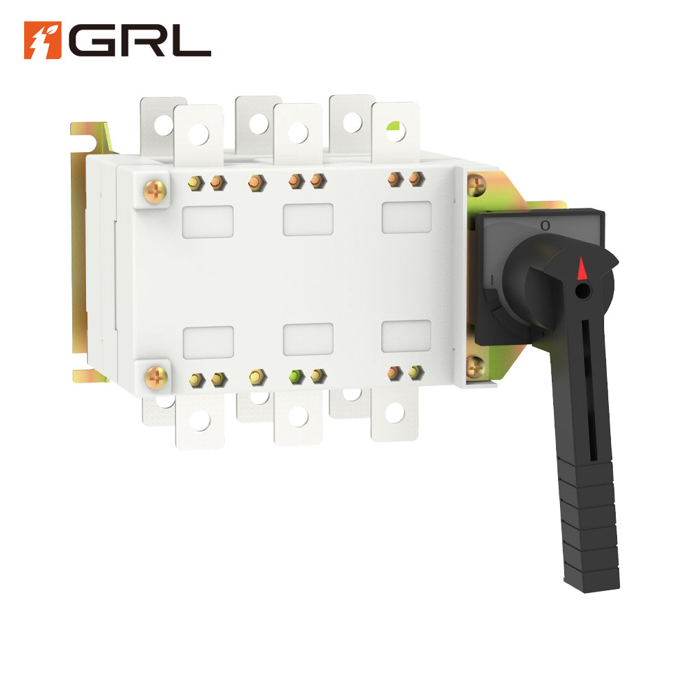
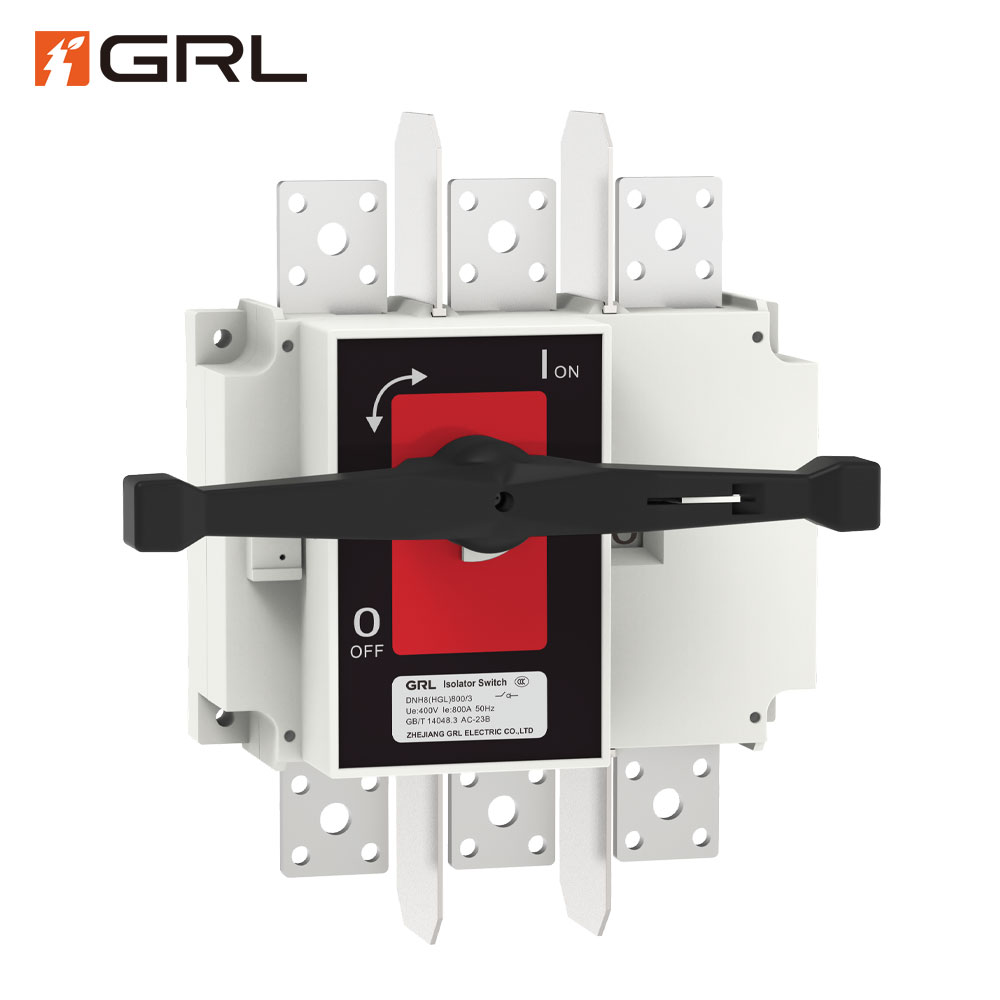
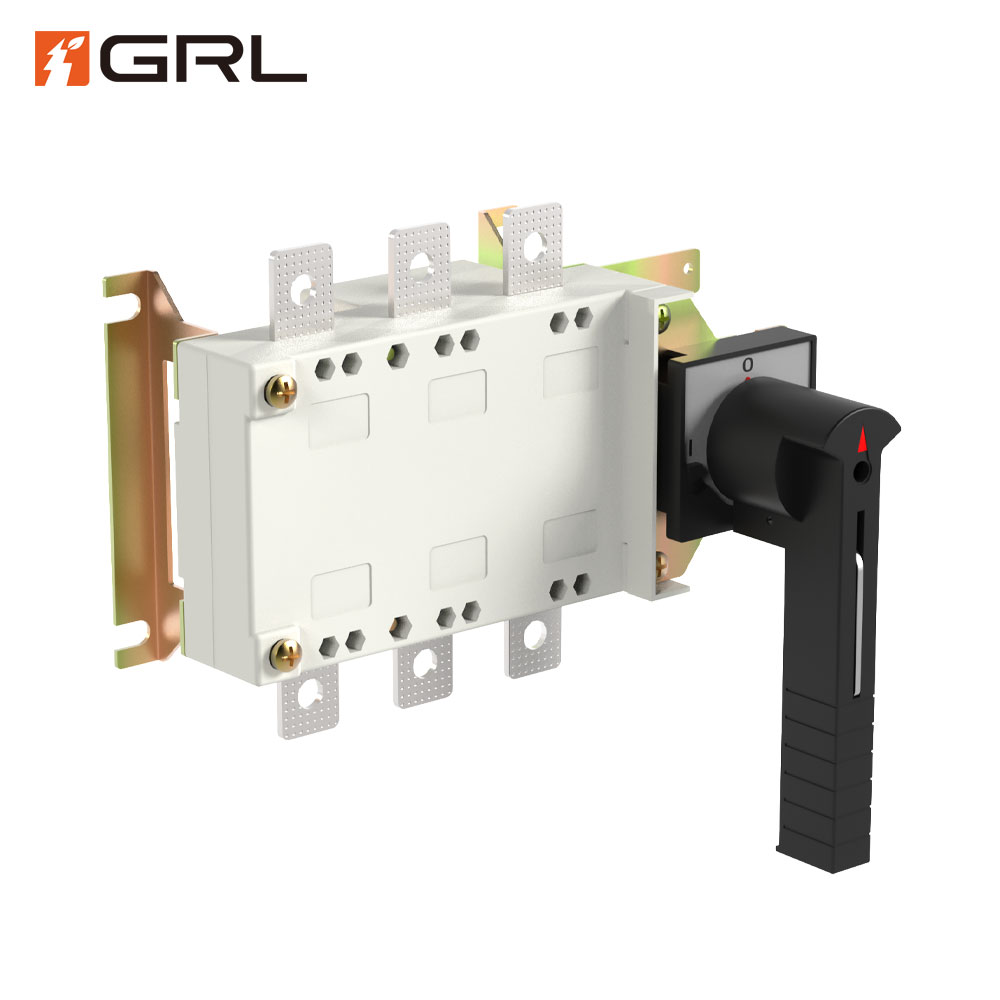
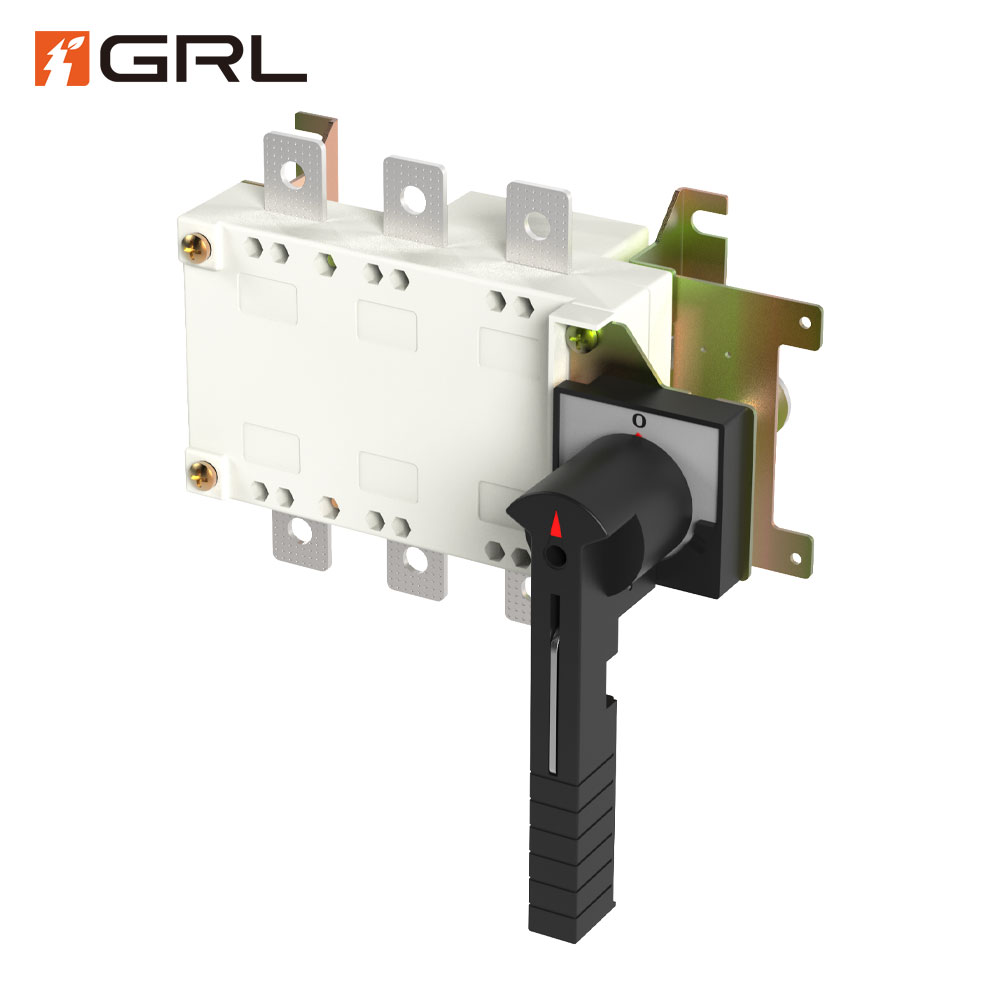
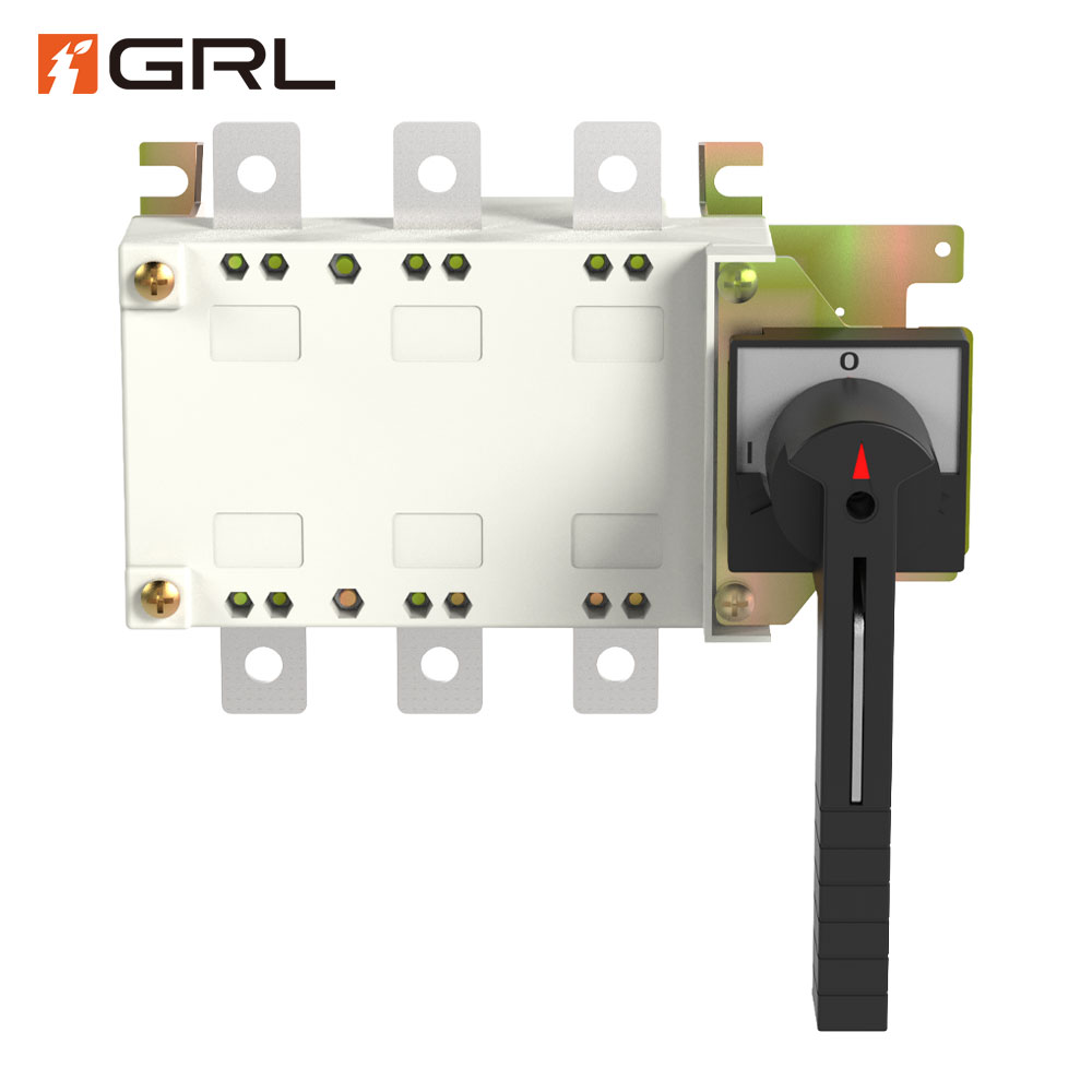
isolator switch on or off

| Specifications | Overall dimension | Installation dimension | |||||||||||||
| In | A | B | C | D | J1 | N | P | R | S | V | W | X | Y | J | K |
| 1000A/3 | 582 | 308 | 242 | 150 | 450 | 53.5 | 120 | 60 | 55 | 35 | 20 | 16.5 | 109 | 353 | 220 |
| 1000A/4 | 697 | 310 | 242 | 150 | 565 | 50.5 | 120 | 60 | 55 | 35 | 20 | 16.5 | 110 | 471 | 220 |
| 1250A/3 | 582 | 336 | 242 | 150 | 450 | 53.5 | 120 | 80 | 68 | 40 | 35 | 16 | 109 | 353 | 220 |
| 1250A/4 | 697 | 338 | 242 | 150 | 565 | 50.5 | 120 | 80 | 68 | 40 | 35 | 16 | 110 | 471 | 220 |
| 1600A/3 | 582 | 336 | 242 | 150 | 450 | 53.5 | 120 | 80 | 68 | 40 | 35 | 16 | 110 | 353 | 220 |
| 1600A/4 | 697 | 338 | 242 | 150 | 565 | 50.5 | 120 | 80 | 68 | 40 | 35 | 16 | 111 | 471 | 220 |


| Specifications | Overall dimension | Installation dimension | ||||||||||||||
| In | A | B | C | D | J1 | N | P | R | S | V | W | X | Y | Y1 | J | K |
| 2000A/3 | 582 | 445 | 330 | 239 | 450 | 53.5 | 120 | 80 | 90 | 40 | 40 | 20 | 102 | 207.5 | 353 | 220 |
| 2000A/4 | 697 | 447 | 330 | 239 | 565 | 50.5 | 120 | 80 | 90 | 40 | 40 | 20 | 103 | 208.5 | 471 | 220 |
| 2500A/3 | 582 | 445 | 330 | 239 | 450 | 53.5 | 120 | 80 | 90 | 40 | 40 | 20 | 102 | 207.5 | 353 | 220 |
| 2500A/4 | 697 | 447 | 330 | 239 | 565 | 50.5 | 120 | 80 | 90 | 40 | 40 | 20 | 103 | 208.5 | 471 | 220 |
| 3150A/3 | 582 | 492 | 330 | 239 | 450 | 53.5 | 120 | 120 | 101 | 50 | 50 | 21 | 75.5 | 235.5 | 353 | 220 |
| 3150A/4 | 697 | 494 | 330 | 239 | 565 | 50.5 | 120 | 120 | 101 | 50 | 50 | 21 | 76.5 | 236.5 | 471 | 220 |
Isolating switches and circuit breakers are two key elements in this field. They play unique but complementary roles in managing circuits. The question that often comes up is: in the setup, which one should be installed first?
Before discussing the sequence, it is necessary to understand the functions of isolating switches and circuit breakers.
An isolating switch is an electrical device that primarily disconnects a portion of an electrical circuit from the main power supply. It is often used for maintenance, repair or to isolate faulty equipment from the electrical system. Unlike circuit breakers, isolating switches cannot interrupt the flow of current during fault conditions. Its main purpose is to provide a protective gap for safe maintenance work.
A circuit breaker is a protective device that automatically interrupts the flow of electricity when an overload or short circuit event occurs. It protects electrical systems from damage caused by excessive current. A circuit breaker is capable of closing and opening a circuit simultaneously under normal and fault conditions.
In a typical electrical system setup, it is recommended to install the isolating switch first, followed by the circuit breaker. Here’s why:
Safety first: Place the isolating switch before the circuit breaker to ensure that the circuit can be safely disconnected during maintenance or repair work. This provides an extra layer of protection for those working on the system.
Visual Confirmation: The isolation switch provides a visible gap in the circuit when open, allowing technicians to visually confirm that the circuit has been isolated before performing any work.
Protect the circuit breaker contacts: By isolating the circuit first, you can protect the circuit breaker contacts from excessive current or potential short circuits that may occur during maintenance activities.
Reduce the risk of arc flash: Arc flash can be very dangerous. Using an isolation switch during maintenance or disconnection can minimize the possibility of arc flash.
Comply with safety standards: Following this sequence is consistent with industry safety standards and best practices for electrical installations.
Exceptions and special circumstances
While the general rule is to install the isolating switch first and then the circuit breaker, there may be specific situations or specialized systems that require a different installation sequence. In this case, it is crucial to consult a qualified electrical engineer or follow the manufacturer’s instructions.
In general, the order of isolating switches before circuit breakers is a basic principle in electrical installations. It prioritizes safety and proper maintenance procedures, ultimately contributing to long-term stable and reliable operation of electrical systems.
Remember, following established industry standards and seeking professional advice when needed can ensure your electrical system operates efficiently and safely.

 Optimized by Seraphinite Accelerator


